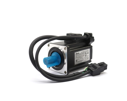
We know that the role of the servo motor is to drive the control object. The torque and speed of the controlled object are controlled by the signal voltage. When the magnitude and polarity of the signal voltage change, the speed and direction of the electric motor rotation also change. Usually servo motor can be classified into AC servo motor and DC servo motor. This article will take you understand AC servo motor device.
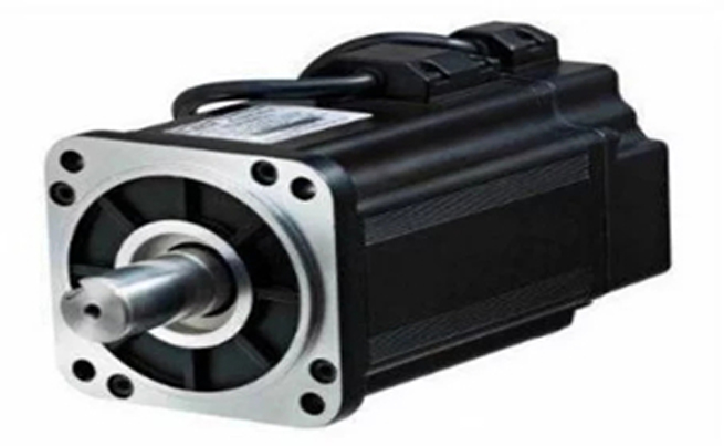
The principle of AC servo motor part is the same as that of a two-phase AC asynchronous motor. There are two windings on the stator including an excitation winding and a control winding. The structure of AC servo motor can be divided into two parts, which are the stator part and the rotor part. The structure of the AC servo motor stator is basically similar to that of the capacitor split-phase single-phase asynchronous motor. The stator is equipped with two windings with a position difference of 90°, one is the field winding Rf, which is always connected to the AC voltage Uf. The other is the control winding L, which is connected to the control signal voltage Uc. Therefore, AC servo motors are also called two servo motors.
The rotor of an AC servo motor is usually made of a squirrel cage, but in order to make the servo motor have a wider speed range, linear mechanical characteristics, no "rotation" phenomenon and fast response performance, it should have two features that the rotor resistance is large and the moment of inertia is small.
When an AC servo motor is used, a constant excitation voltage Uf is applied to both ends of the excitation winding, and a control voltage Uk is applied to both ends of the control winding. When voltage is applied to the stator winding, the servo motor will quickly rotate. The current flowing into the excitation winding and the control winding generates a rotating magnetic field in the motor. The rotation of the rotating magnetic field determines the direction of the motor. When the voltage applied to any winding is reversed, the direction of the rotating magnetic field changes, and the motor's direction has also changed. In order to form a circular rotating magnetic field in the motor, it is required that there should be a 90 degree phase difference between the excitation voltage Uf and the control voltage UK. Common methods are as followings.
1. Use the phase voltage and line voltage of the three-phase power supply to form a 90-degree phase shift.
2. Use any line voltage of the three-phase power supply.
3. Use phase shift network.
4. Connect capacitors in series in the excitation phase.
1. Since there are no brushes and commutators, it works reliably and has low maintenance and maintenance requirements.
2. It is more convenient to dissipate heat from the stator winding.
3. The inertia is small and it is easy to improve the speed of the system.
4. It adapts to high-speed and high-torque working conditions.
 English
 日本語
日本語 한국어
한국어 français
 Deutsch
 Español
 italiano
 русский
 العربية
 Türkçe
 Jawa
Jawa