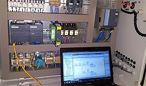
During the operation of the motor, real-time monitoring of basic parameters such as current, speed, and relative position of the rotating shaft in the circumferential direction etc. can clarify the status of the motor and the machinery and equipment being dragged, and further control the operating conditions of the motor and machinery in real time to complete many special functions such as the servo and speed regulation etc. As front-end measurement components, the use of encoder product not only greatly simplifies the measurement system, but also is precise, safe, reliable, and powerful. This article will take you understand how small encode component on motor works.
We know that precise encoder device is a rotary sensor that converts the position and displacement of rotating parts into a series of digital pulse signals. This pulse signal is collected and processed by the control system, and a series of instructions are issued to adjust and change the operation of machinery and equipment. If the encoder is combined with a gear bar or a spiral screw, it can also be used to measure the position and displacement of linear moving parts.
Usually the encoders are used in motor output signal feedback systems, measurement and control equipment. The internal structure of the encoder consists of two parts. One is an optical code disc, and the other is a receiver. The basic optical parameters generated by the rotation of the optical code disc are converted into corresponding electrical basic parameters, and the signal of the drive power is output according to the pre-amplification and signal processing system in the frequency converter. Generally, the rotary encoder can only feedback a speed signal, which is compared with the set value and fed back to the inverter execution unit to adjust the motor speed.
According to the detection principle, the encoder can be divided into optical, magnetic, inductive and capacitive. According to its scale method and signal output method, it can be divided into three types, incremental type encoder , absolute type encode and mixed encoder.
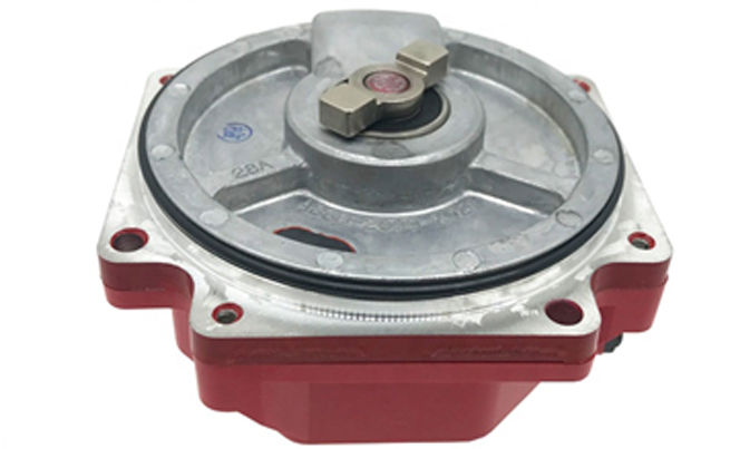
For incremental encoder device, its position is determined by the number of pulses calculated from the zero mark; it converts the displacement into a periodic electrical signal, and then converts this electrical signal into a counting pulse, and the number of pulses represents the magnitude of the displacement.
The position of the absolute encoder device is clearly defined by the reading of the output code. The reading of the output code for each position within a circle is unique, and will not lose a one-to-one correspondence with the actual position when the power is disconnected. Therefore, the incremental encoder is switched on again after the power is off, and the position reading is current. And each position of the absolute encoder corresponds to a clear digital code, so its indication value is only related to the start and end positions of the measurement, and it has nothing to do with the intermediate operation process of the measurement. The absolute encoders are divided into single-turn encoder and multi-turn encoder.
 English
 日本語
日本語 한국어
한국어 français
 Deutsch
 Español
 italiano
 русский
 العربية
 Türkçe
 Jawa
Jawa