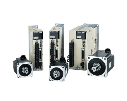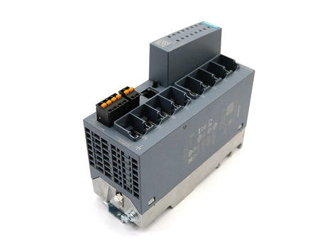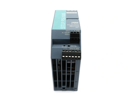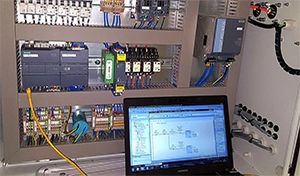
The spindle drive controller refers to a controller that sends pulse signals to the driver to control the Fanuc spindle drive, and is mostly used in CNC machine tool processing. In this article, we will introduce the common faults and solutions of the spindle drive Fanuc controller.
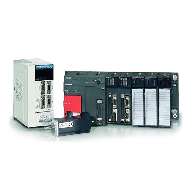
The cause of the fault is that the Fanuc ac spindle motor speed is too high or the motor speed cannot be detected
Check carefully whether the tachogenerator of the DC fanuc spindle motor has voltage output
Check whether the excitation voltage of the motor is normal. It is 13. 8V when stopping, the current is 2.8A, while the voltage is 32V when starting, and the current is 6.8A
Check the wiring for errors, including power line A, H, excitation line J, K
The setting of the control board is wrong, check if any maintenance personnel have changed the setting of the shorting bar or potentiometer
There are two possible causes of the fault. The action of the thermal relay of the DC Siemens spindle motor is faulty or the action of the thermal relay inside the Mitsubishi servo drive unit is faulty.
Touch the surface of the DC spindle motor with your hand to see if it is very hot. If it is very hot, stop it, and turn it on after cooling down to see if there is an alarm.
Check whether the mechanical load or cutting amount is too large.
Observe whether there is an alarm as soon as it is turned on, if it is, check whether the control board CN2 is not plugged in, and check whether the thermal protection switch of the motor is off, and whether the thermal protection switch TH of the unit is off.
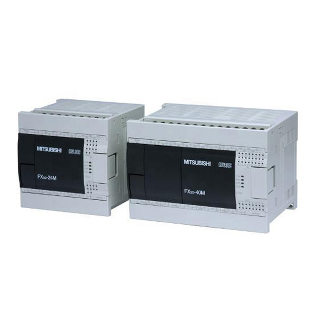
The cause of the fault is the main circuit short circuit or poor insulation, or the control fanuc drive board failure causes the main circuit current to be too large, and the phase-to-phase short circuit is caused by the thick film circuit failure on the board during deceleration.
Check the insulation of the DC servo motor or the insulation of the main circuit, if the insulation resistance is less than 1MO or less, replace the corresponding parts
Use a multimeter to check whether all 12 SCRs in the main circuit are short-circuited, and replace the corresponding bad SCRs.
If there is an over-current alarm while burning the insurance, you can follow the above-mentioned over-current alarm
Use a multimeter to check whether the input voltage is too high and cannot exceed 250V
Replace the main control servo drive board.
The cause of the fault is that the Mitsubishi driver unit or DC spindle motor does not execute after the system sends the command, or the control board detects that the current deviation value is too large, so wait for the deviation value to become smaller
Observe what alarms appear on the servo unit after the command is given. If the servo has OVC, it may be mechanically stuck.
If the servo does not have any alarms, check whether the wiring or connection plugs are normal at this time, including the motor power line, motor excitation line, CN1 plug, R/S/T three-phase input line, CN2 plug, and the control board and unit connect. If everything is normal, replace the control board and check.
 English
 日本語
日本語 한국어
한국어 français
 Deutsch
 Español
 italiano
 русский
 العربية
 Türkçe
 Jawa
Jawa