It is annoying when there are faults appeared on your Siemens touch screen. Then how to repair? In this article, we will talk about the common faults and causes of Siemens touch screen product and share with you the corresponding solutions.
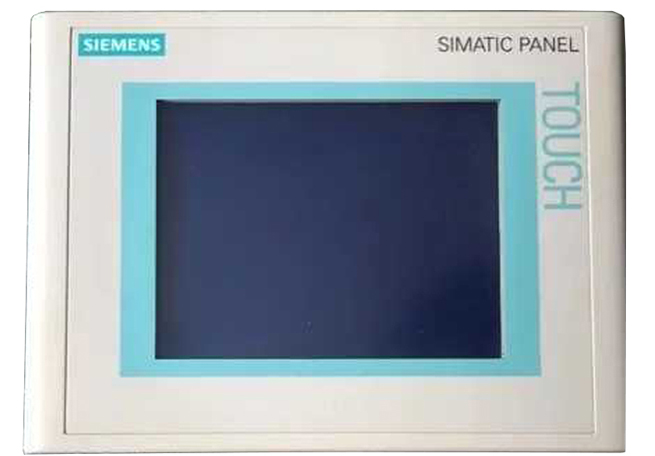
Phenomenon 1: The position touched by the finger does not overlap with the mouse arrow.
Reason 1: After installing the driver, when correcting the position, you did not touch the center of the target vertically.
Solution 1: Correct the position again.
Phenomenon 2: Accurate touch in some areas, and there is deviation in some areas.
Reason 2: The surface acoustic wave touch screen has a large amount of dust or scale accumulated on the sound wave reflection stripes of the periphery of the surface acoustic wave touch screen, which affects the transmission of the sound wave signal.
Solution 2: Clean the touch screen device, and pay special attention to clean the sound wave reflection stripes on the four sides of the touch screen. Do remember to disconnect the power supply of the touch screen control card when cleaning.
Phenomenon: When the screen is touched, there is no movement of the mouse arrow and no position change occurs.
Reason: The reasons for this phenomenon are as follows:
1. The dust or scale accumulated on the sound wave reflection stripes of the four periphery of the surface acoustic wave touch screen is very serious, which makes the touch screen unable to work;
2. The touch screen is malfunctioning.
3. The touch screen control card fails.
4. The touch screen signal line is faulty.
5. The touch screen serial port is malfunctioning.
6. The touch screen operating system fails.
7. The touch screen driver installation error.
The touch screen inverter device used by Siemens inverter is insulated gate bipolar transistor. Its control feature is high input impedance and small gate current, so the driving power is small, and it can only work in the on-off state, and cannot work in the amplified state. Its switching frequency can reach very high, but the antistatic performance is poor. Whether the insulated gate bipolar transistor component is out of order can be measured and judged with an ohmmeter. The specific steps are as follows:
1. Disconnect the inverter power supply.
2. Disconnect the controlled motor.
3. Use an ohmmeter to measure the impedance of the output terminal and the dc connection terminals a and d, and each test is performed twice by changing the polarity of the ohmmeter. If the inverter's insulated gate bipolar transistor is intact, it should be from u2 to a Low resistance value. Otherwise, it should be high resistance value. Similarly it should be high resistance value from u2 to d; on the contrary, it is low resistance value. The same is for other phases. When the insulated gate bipolar transistor is disconnected, both times are high resistance values, if short-circuited, both are low resistance values.
 English
 日本語
日本語 한국어
한국어 français
 Deutsch
 Español
 italiano
 русский
 العربية
 Türkçe
 Jawa
Jawa
