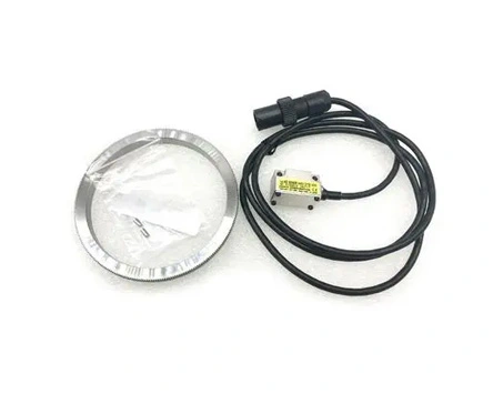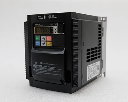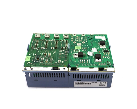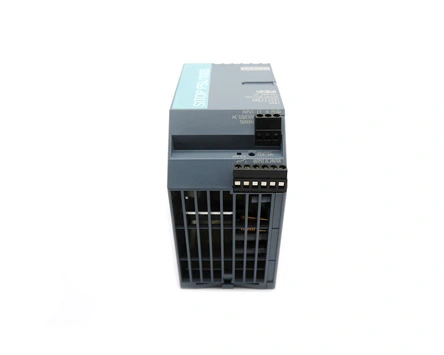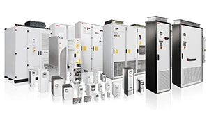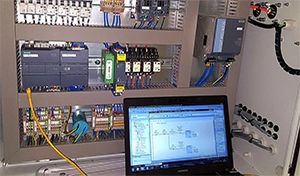
PLC is mainly composed of central processing unit, input interface, output interface, communication interface and other parts, wherein CPU is the core of PLC, I/0 component is connected to the interface circuit between the field equipment and the CPU, communication interface is used to connect with the programmer and the upper computer. For integral PLC, all components are installed in the same housing; For modular PLC, each functional part is packaged independently, called module or template, each module is connected through the bus, mounted on the rack or rail.
PLC control system fault is divided into software fault and hardware fault two parts. PLC system includes central processor, main box, expansion box, I/O module and related network and external equipment. Field production control equipment includes I/0 ports and field control testing equipment, such as relays, contactors, valves, motors, etc.
PLC has self-diagnosis ability, when the module function error occurs, it can often alarm and respond according to the pre-procedure, and can be judged by the fault indicator light. When the power supply is normal, the indicators are also normal, especially the input signal is normal, but the system function is not normal (no output or chaos), in line with the first easy after difficult, first soft after hard maintenance principle first check whether there is a problem with the user program.
The user program is stored in the RAM of the PLC, and is volatile. When the backup battery fails, the system power supply fails, the possibility of program loss or disorder is very large, and strong electromagnetic interference will also cause program errors.
① The I/O port of the PLC is faulty.
The failure of the I/O module is mainly the influence of various external interference, first of all, it must be used in accordance with the requirements of its use, and cannot be reduced at will, and then analyze the main interference factors, and isolate or deal with the main interference sources.
② PLC host system failure
A. The power supply system is faulty. Power supply in continuous operation, heat dissipation, voltage and current fluctuations impact is inevitable.
B. Communication network system failure. Communication and network are likely to be affected by external interference, and the external environment is one of the biggest factors causing the failure of communication external equipment. The damage of the system bus is mainly due to the PLC plug-in structure, long-term use of the plug and remove module will cause local printing board or bottom plate, plug-in interface and other bus damage, under the influence of air temperature changes, humidity changes, the aging of the bus plastic, the aging of the printed line, the oxidation of the contact point, etc., are the causes of the system bus loss.
③ field control equipment failure
A, relay, contactor. To reduce such failures, we should try to use high-performance relays, improve the use environment of components, and reduce the frequency of replacement. If the site environment is harsh, the contactor contact is easy to ignite or oxidize, and then heat deformation until it can not be used.
B, valves or ram and other equipment. Long-term use of lack of maintenance, mechanical and electrical failure is the main cause of failure, because the key parts of such equipment, relative displacement is generally large, or through several steps such as electrical conversion to complete the valve or ram position conversion, or the use of electric actuator to push and pull the valve or ram position conversion, Mechanical, electrical, hydraulic and other links are slightly not in place will produce errors or failures.
C, switches, limit positions, safety protection and on-site operation of some components or equipment failure, the cause may be because of long-term wear, or long-term use and rust aging. The troubleshooting of such equipment faults is mainly reflected in regular maintenance to keep the equipment in good condition at all times. For limit switches, especially limit switches on heavy equipment, in addition to regular maintenance, multiple protective measures should be added in the design process.
D. The sub-devices in the PLC system, such as junction boxes, wire terminals, bolts and nuts, are faulty. The reason for this kind of failure is mainly caused by the production process of the equipment itself, the installation process and the long-term ignition and rust. According to engineering experience, this kind of fault is generally difficult to find and repair. Therefore, the installation and maintenance of the equipment must be carried out in accordance with the installation process of the installation requirements, leaving no hidden dangers of the equipment.
E. Sensor and meter failure. This kind of fault is generally reflected in the abnormal signal in the control system. When such equipment is installed, the shielding layer of the signal line should be reliably grounded in a single end, and be laid separately from the power cable as far as possible, especially the high-interference inverter output cable, and software filtering should be carried out inside the PLC.
F, power, ground and signal line noise (interference) failure.
① a petrochemical device Siemens PLC (S7-300, CPU315-2DP) suddenly stopped running when it was in use.
Fault check and analysis: check the alarm lamp, program, and power supply. When checking the alarm, it is found that the BAT on the CPU is on. When checking the program, it was found that there was no troubleshooting for battery failure. Troubleshooting: Replace the CPU battery and handle the battery failure in the program.
② one night, the compressor PLC and the main control PLC communication suddenly interrupted, the main control DCS display the compressor PLC and the main control PLC communication interruption alarm, the compressor control room in the motor signal on the main control synthesis DCS are displayed in red (stop state), some flow, pressure, temperature and other signals in the compressor control room, The high and low alarms are displayed on the main control synthetic DCS. Due to the communication interruption, some important interlocks in the compressor control room can not be sent to the main control, which makes the whole plant shut down.
Fault inspection and analysis: Theoretically speaking, there are two main reasons for the communication interruption between the compressor PLC and the main control PLC: one is that the software is not synchronized; The other is due to hardware failures such as CP525 cards and CPU cards.
First from the software aspect to deal with. The synchronization operation was carried out in the main control PLC, and the 14th digit of the data word DW13 was forced to communicate, but the communication was still not established, it seems that the main control PLC was not caused by the synchronization. Then it is synchronized in the compressor PLC operation, forcing the communication data word MW10 in the 14th bit, the result communication is established. Therefore, it is confirmed that the reason for the communication interruption between the PLC and the main control PLC of the compressor is caused by the non-synchronization of the compressor program, and the reason for the non-synchronization of the program is the external electromagnetic interference.
Troubleshooting: In order to avoid the recurrence of such failures, the shielding of the control room should be strengthened, and the use of communication tools such as mobile phones is prohibited in the control room.
③ Siemens PLC (S7-300) SF light alarm
Fault inspection and analysis: SF lamp alarm indicates that the input point is faulty. Troubleshooting: Check the working status of each input point. During the inspection, it is found that a temperature transmitter on site has no input signal, and the fault disappears after processing.
④ The outside of a PLC input point is not connected (even if the connection line on the input terminal is disassembled), but the input point has actually been connected and the corresponding input indicator light is steady on fault analysis: Determine that the adjacent terminals of the terminal have been connected, and there is iron filings between the input terminals of the PLC, resulting in the input point being connected, or the input point has been damaged.
Troubleshooting: Disassemble the wiring of all the input terminals of PLC, find that there are many iron chips on the input terminal block, blow the iron chips on the terminals, and then restore the wiring, the fault is eliminated.
⑤ control system PLC digital input card SF light turned red
Fault inspection and analysis: After the card power supply is re-powered, the fault phenomenon still exists; After restarting the PLC, the fault indicator is still red. Therefore, after checking the on-site signals received by the card piece one by one, it was found that there was an abnormal signal switch. After measuring with a multimeter, it is found that the loop resistance is infinite, which indicates that the return switch is broken and detected by the digital input card. Troubleshooting: After the spare part is replaced, the fault indicator is off.
⑥ pelletizer PLC control system analog input card received the field signal on the DCS indicates infinity
Fault inspection and analysis: The analysis may be that the communication cable connected between the field pressure transmitter and the junction box is faulty, so the communication cable is replaced, but the phenomenon is still the same. After careful inspection and analysis of the entire loop, it is found that there are three easy places in the loop, the pressure transmitter itself, the communication cable, the clamp, the pressure transmitter, the communication cable have been excluded. When the card was taken apart, it was found that a small integrated block inside had been burned. Troubleshooting: Replace the card.
⑦ the two PLC mutual hot spare controller only one can run, the other is always stopped
Fault inspection and analysis: Power off the entire control cabinet, start two PLC hosts at the same time after power transmission or only one PLC host runs. After querying relevant data, it is found that the two system function blocks OB70 and OB72 are responsible for redundancy faults. If the two function blocks are not inserted, the system redundancy is lost, that is, only one CPU can run. Troubleshooting: After the two system function blocks are inserted, the control system returns to normal
A PLC control system that has been shut down for a period of time cannot be started after being powered on
Fault inspection and treatment: the maintenance personnel think that the program is wrong after the inspection, it is natural to insert the EPROM card into the PLC, always clean the copy program, restart after completion, the fault is still, because the program is not large, read the program on the EPROM one by one, and the instructions on the manual are found to be exactly the same after checking, and the repeated copy is considered to be PLC hardware fault.
The backup program is called up by PG and compared with the program on EPROM. The result shows that the command table is the same, but the program storage address has changed. After the backup program is sent to PLC, the device runs normally. It can be seen that the program on the EPROM also has an error, erase and re-write the problem solved.
PLC hardware damage or software operation error probability is very low, check the fault, the focus should be placed on the PLC peripheral electrical components, PLC fault is mostly peripheral interface signal failure, maintenance, as long as the PLC has part of the control of the normal operation, there is no need to doubt the PLC program problems. Confirm that the operation program has output, and the PLC interface has no output, it is the interface circuit fault. The hardware failure of PLC system is more than the software failure, mostly caused by the external signal is not satisfied or the fault of the execution component, rather than the PLC system problem.
The fault can be determined according to the PLC input and output state. PLC input and output signals are through the I/O channel, some faults will be reflected in the I/O interface channel, sometimes by observing the I/O interface status, you can find the cause of the failure.
PLC has a self-diagnosis function, check the fault according to the alarm information, identify the cause and determine the fault location, is also the basic means and methods to check and eliminate the PLC fault. First determine whether the fault is global or local, the upper computer displays a number of control components are not working normally, prompting a lot of alarm information, you need to check the CPU module, memory module, communication module and power supply and other public parts.
Experience shows that most of the failures of the PLC control system are checked out by the PLC program. The actions of the PLC control system are completed in a certain order, observe the action process of the system, compare the fault and the normal situation, most of the doubts can be found, and judge the cause of the failure.
Some faults can be directly displayed on the screen alarm reasons, although some have alarm information, but does not directly reflect the cause of the alarm; Some faults do not produce alarm information, but some actions are not executed; In the above two cases, tracking the operation of the PLC program is an effective way to check the fault.
 English
 日本語
日本語 한국어
한국어 français
 Deutsch
 Español
 italiano
 русский
 العربية
 Türkçe
 Jawa
Jawa