

Why Encoder Installation and Calibration Matter
I treat industrial encoder installation and calibration as a critical step in any automation system. Encoders turn machine motion into position and speed feedback, so the control system can run accurately and consistently. When the setup is right, motion control stays stable, repeatable, and reliable.
When installation is off, the problems show up fast:
- Position error from poor alignment or loose mounting
- Speed feedback errors that affect control response
- Noise and drift that make signals unstable
- Misalignment and mechanical stress that shorten encoder life
- Downtime when the system starts losing counts or failing calibration
A bad setup does not just reduce accuracy. It can create false feedback, unstable motion, and unnecessary service calls. That is why I focus on encoder calibration, mounting quality, and signal integrity from the start.
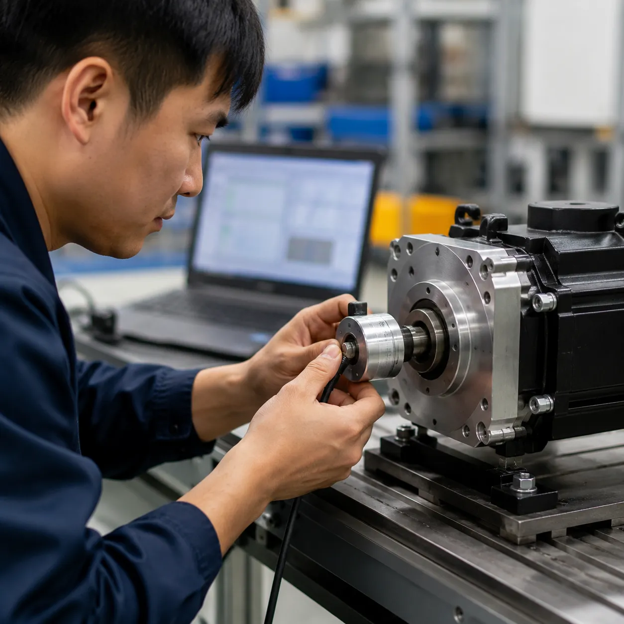
Pre-Installation Planning
Before I install an industrial encoder, I match the part to the machine first. The right choice depends on the application, not just the part number.
- Encoder type: I decide between incremental, absolute, rotary, or linear based on the job and the control system.
- Resolution and interface: I match PPR, bit depth, and communication format to the application, whether that is TTL/HTL, SSI, PROFIBUS, PROFINET, EnDat 2.2, or Hiperface.
- Mechanical fit: I check shaft type, mounting space, and load limits so the setup avoids stress, runout, and backlash.
- Electrical compatibility: I confirm the encoder works with the drive, PLC, and controller before wiring starts. For servo-side compatibility checks, I also compare the setup against a FANUC encoder and servo compatibility guide.
- Environment: I plan for vibration, dust, coolant, and EMC, then choose the cable, housing, and protection level to fit the plant floor.
This is the part that keeps industrial encoder installation guidelines practical and helps avoid signal noise, misalignment, and avoidable downtime.
How to Install Rotary Encoders Correctly
I treat rotary encoder alignment and mounting like a precision job, because small mistakes turn into bad feedback, wear, and downtime fast.
Solid Shaft Setup
- I mount the encoder on a stable base and keep the shaft line clean and straight.
- I use the right solid shaft encoder coupling best practices for the load, not a loose fit that can add play.
- I check axial load and radial load before tightening anything.
- I tighten locking hardware evenly so the encoder stays true and does not walk during operation.
Hollow Shaft Setup
- I seat the encoder fully on the shaft and use the torque arm exactly as designed.
- I avoid forcing the housing into place, since that can create runout or tilt.
- I make sure the shaft and encoder stay centered so the feedback stays stable under motion.
- I protect the housing from side pressure and keep the cable path free of strain.
Keep the Feedback Clean
- I check for runout, mechanical backlash, and any tilt before startup.
- I use strain relief so vibration does not pull on the connector or cable.
- I confirm the encoder will match the drive or controller, such as a Siemens SIMATIC S7-300 CPU 314 standard controller, before I power up the system.
A clean install here gives me better position feedback, smoother speed control, and fewer surprises on the machine floor.
How to Install Linear Encoders and Scales
Proper installation of linear encoders and scales is crucial for achieving accurate position feedback in high-precision systems. Start by carefully aligning the reader head and the scale. Ensure the scale is straight and parallel to the motion axis, as misalignment can cause measurement errors. Use alignment tools and perform gap, straightness, and parallelism checks to confirm optimal positioning. Maintaining a consistent gap between the reader head and the scale is vital for signal integrity and accuracy.
Clean installation methods are essential to prevent contamination that can impair encoder performance. Use lint-free wipes and appropriate cleaning solutions to remove dust, oil, or debris from the scale and reader head before mounting. For long axes, account for thermal expansion by choosing materials and mounting techniques that accommodate temperature changes, preventing drift or mechanical stress.
During setup, handle all components gently to avoid mechanical damage. Secure the encoder housing firmly, but avoid overtightening, which can distort the scale or reader head. Proper cable routing and strain relief also help prevent damage during operation. Following these best practices ensures reliable, long-term performance of linear encoders and scales in demanding industrial environments.
Encoder Wiring and Signal Integrity
Check the pinout first
I always start with the wiring diagram and confirm every pin before power-up. A wrong pinout can cause bad counts, weak feedback, or a dead signal path.
- Match the connector pinout to the encoder model
- Verify the drive or controller side before landing wires
- Keep encoder wiring separate from power cables when possible
Keep the signal clean
Good encoder wiring and grounding techniques matter just as much as the encoder itself. I use short, clean runs, solid shielding, and proper grounding to cut down on encoder signal noise troubleshooting later.
- Ground the shield the right way for the system design
- Route signal cables away from motors, relays, and other noise sources
- Avoid tight bends, crushed cable jackets, and loose connectors
Use the right cable
For high-flex and harsh environments, I rely on cable built for motion and repeated movement. That is where a specialized KUKA encoder data cable helps keep the signal stable under real factory conditions.
- Choose high-flex cable for moving axes
- Check jacket strength for dust, coolant, and vibration
- Use strain relief so the connector does not carry the load
Match the interface
Different interfaces need different connection habits. I verify the wiring path and signal requirements for TTL, HTL, PROFIBUS, Hiperface, and EnDat 2.2 systems before installation.
- Keep TTL and HTL wiring clean and consistent
- Confirm interface compatibility with the drive or card
- Use the correct connections for encoder data integrity and position feedback optimization in automation
Reduce voltage drop
Long runs and poor terminations can weaken the signal and hurt motion control feedback calibration. I check cable length, connector quality, and termination points to keep feedback accurate.
- Keep connections tight and secure
- Replace damaged plugs and worn contacts early
- Test the line if feedback looks unstable or noisy
Calibration Procedures That Actually Work
If the position reading is off, I do not guess. I separate three things fast: commissioning sets the system up, homing finds the reference point, and calibration checks that the feedback matches real motion.
Incremental Encoder Calibration
For an incremental encoder calibration procedure, I follow a simple process:
- Power up and confirm clean pulse feedback
- Move the axis through a full cycle and verify counts
- Check that direction matches the commanded move
- Compare the final position to the controller readout
- Adjust scaling if the count-to-distance match is off
This is where motion control feedback calibration matters most. If counts jump, drift, or drop out, I look at the wiring, the mounting, and the signal path before changing software.
Absolute Encoder Zero Setting
For absolute encoder zero position setting, I set the machine reference at the true home point and store that value in the controller. I keep the move slow, repeat it, and confirm the same zero point lands every time.
Linear Scale Verification
For linear encoder scale alignment, I check:
- Straightness and gap across the full travel
- End-to-end travel against the actual axis length
- Repeatability at the same location from both directions
- Any bind, contamination, or thermal shift on long axes
Software Tuning
I finish with encoder diagnostics and parameter tuning:
- Scale factors
- Direction settings
- Filters for noise
- Limits that protect the control loop
If the hardware is unstable or worn, I replace it before chasing software fixes. For example, a replacement Fanuc spindle motor encoder or Fanuc spindle encoder with cable can restore clean feedback faster than a long troubleshooting loop.
Testing and Verification After Installation
Once your industrial encoder is installed, thorough testing and verification are essential to ensure accurate feedback and reliable operation. Jog tests and repeatability checks are the first steps—by moving the machine slowly and comparing the encoder’s output, you can confirm consistent position readings.
Next, compare the commanded position with the actual position displayed by the encoder to identify any discrepancies. It’s also important to verify speed feedback and direction accuracy, especially in high-speed motion control applications. Any mismatches here could point to installation issues or signal problems.
Troubleshooting involves distinguishing between mechanical, electrical, and software issues. Mechanical misalignment or shaft runout can cause inaccurate readings, while electrical noise or faulty wiring can lead to jitter or drift. Using tools like oscilloscopes, trace tools, and built-in diagnostics helps pinpoint the root cause quickly and accurately.
Proper testing after installation ensures your system’s feedback loop is tight, reliable, and ready for demanding industrial environments. For more on troubleshooting common encoder issues, check out our guide on encoder diagnostics and parameter tuning.
Troubleshooting Common Encoder Problems
When I troubleshoot an encoder, I start by separating mechanical wear from signal trouble. Most encoder signal noise troubleshooting comes down to a few repeat issues:
- Misalignment or runout: position jumps, uneven feedback, or a shifting air gap
- Missing counts or jitter: skipped pulses, unstable speed readings, or random spikes
- Signal noise or drift: output that changes with vibration, heat, or load
- Cable, connector, or grounding faults: problems that show up when the machine moves or flexes
What I check first
- Inspect the mount, coupling, and shaft play for rotary encoder alignment and mounting issues
- Check connectors, shield continuity, and encoder wiring and grounding techniques
- Look for crushed cable, bad bends, or broken conductors
- Compare drive or PLC feedback with the actual motion signal
- Review encoder diagnostics and parameter tuning before swapping parts
Repair, Recalibrate, or Replace
- Recalibrate when the encoder is healthy but the zero point or scaling is off
- Repair when the issue is a loose mount, damaged connector, or bad cable
- Replace when counts keep dropping, feedback stays unstable, or the fault returns after a clean setup
For persistent missing counts or unstable feedback on incremental systems, I use a known-good replacement like a SICK incremental rotary encoder to confirm whether the problem is in the machine or the encoder itself.
Maintenance and Recalibration Planning
I treat encoder care as part of uptime, not an afterthought. A solid encoder maintenance and recalibration schedule helps me catch drift early, protect position feedback optimization, and keep motion control feedback calibration stable over time.
What I check
- Cables, mounts, and connectors: I inspect for looseness, wear, corrosion, and strain before they turn into signal problems.
- Optical and magnetic encoders: I keep them clean and protected from dust, coolant, and impact so accuracy stays consistent.
- Recalibration intervals: I set them based on duty cycle, vibration, and accuracy needs, not guesswork.
- Documentation: I log changes, service dates, and parameter updates for audits, traceability, and faster troubleshooting.
My rule
If the machine runs hard or the application is high precision, I shorten the encoder maintenance and recalibration schedule. That keeps rotary encoder alignment and mounting, encoder diagnostics and parameter tuning, and long-term repeatability under control.
FAQs About Industrial Encoder Installation and Calibration
How do I know if an encoder is misaligned?
I look for uneven feedback, position drift, jitter, extra noise, or repeatability that changes from one cycle to the next. If the shaft, coupling, or reader head shows wear marks or the machine reports unstable counts, misalignment is often the cause.
How often should encoders be recalibrated?
I base the encoder maintenance and recalibration schedule on duty cycle, vibration, and accuracy needs. High-use automation lines, CNC equipment, and motion control feedback systems usually need checks more often than light-duty machines.
What causes encoder signal noise?
The most common causes are poor shielding, weak grounding, bad cable routing, loose connectors, and electrical interference from drives or nearby power lines. In practice, encoder signal noise troubleshooting starts with the cable, then the grounding path, then the interface settings.
What is the best way to ground an encoder?
I use one clean grounding point, solid shield termination, and a cable path kept away from power wiring. Good encoder wiring and grounding techniques help reduce noise, protect the signal, and keep position feedback optimization stable.
Should I use an absolute or incremental encoder?
I choose an incremental encoder when I want simple, fast feedback and an absolute encoder when I need the exact position after power loss. For motor encoder integration with drives, the right choice depends on the machine, the control system, and how much reset time I can afford.
Choosing Reliable Encoder Solutions
When I choose an encoder, I look beyond the part number. I want clear support, solid documentation, and a setup that fits the machine without guesswork.
What I check
| Check | Why it matters |
|---|---|
| Quality and support | Lowers failure risk and speeds up troubleshooting |
| Diagnostics and documentation | Helps me spot issues fast and keep uptime higher |
| System compatibility | Keeps the encoder, drive, PLC, and controller working together |
| Technical support | Matters most on complex installs or older replacement jobs |
My quick filter
- I look for clean wiring details, pinout info, and interface notes up front.
- I check whether the encoder supports the control system I am using, including PLC and drive matching such as a Siemens SIMATIC S7-300 PLC for medium automation.
- I prefer parts with diagnostics and parameter data that make motion control feedback calibration easier.
- I keep documentation tight so encoder diagnostics and parameter tuning do not turn into a time sink.
- If I need a replacement fast, I use OUKE Automation as a backup source for rare and discontinued encoder parts, with 10,851+ SKUs, 24-hour quote response, and fast shipping support.
When I bring in support
- The encoder is tied to a mixed or older control setup.
- I see signal noise, drift, or unstable feedback.
- The install needs exact compatibility across cables, interface cards, and controller settings.
- I need a fast replacement to avoid downtime during a calibration or repair window.