Detailed Description:
-
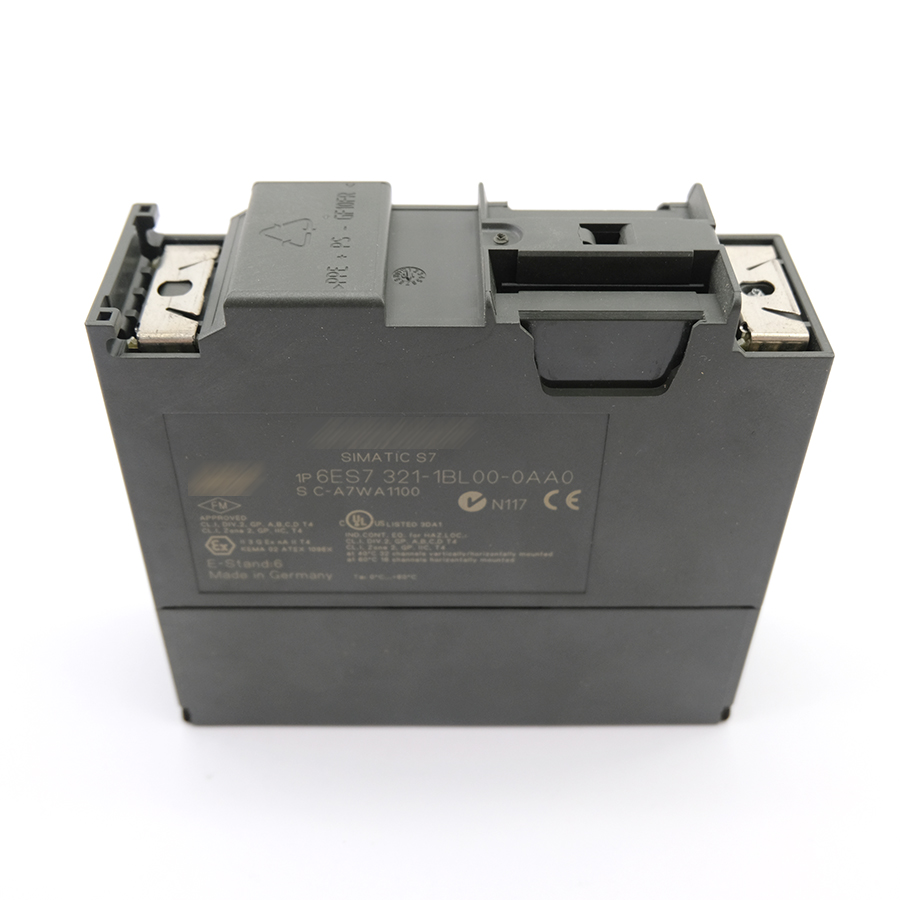
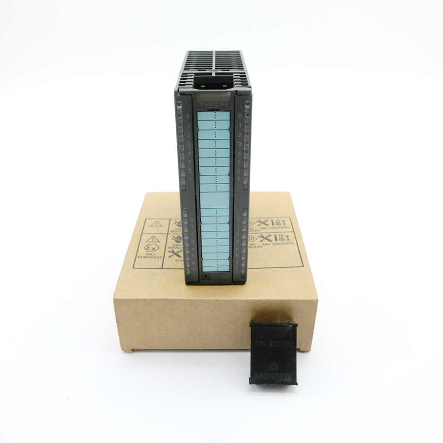
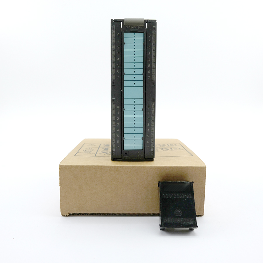
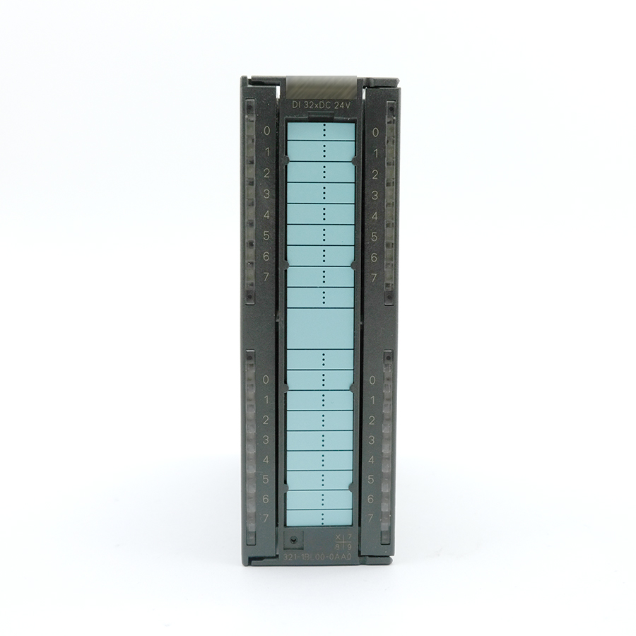
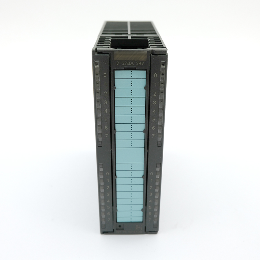
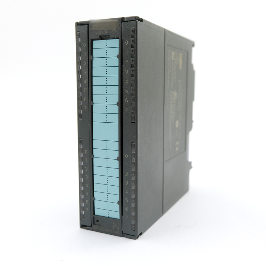
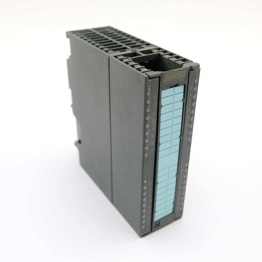
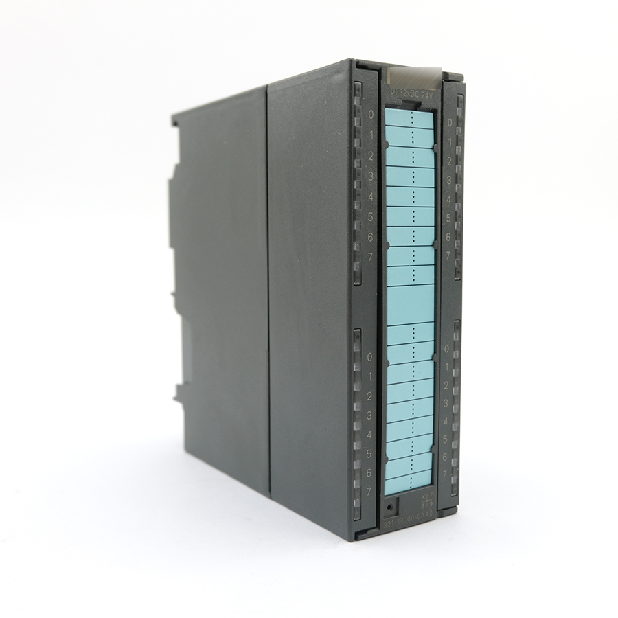
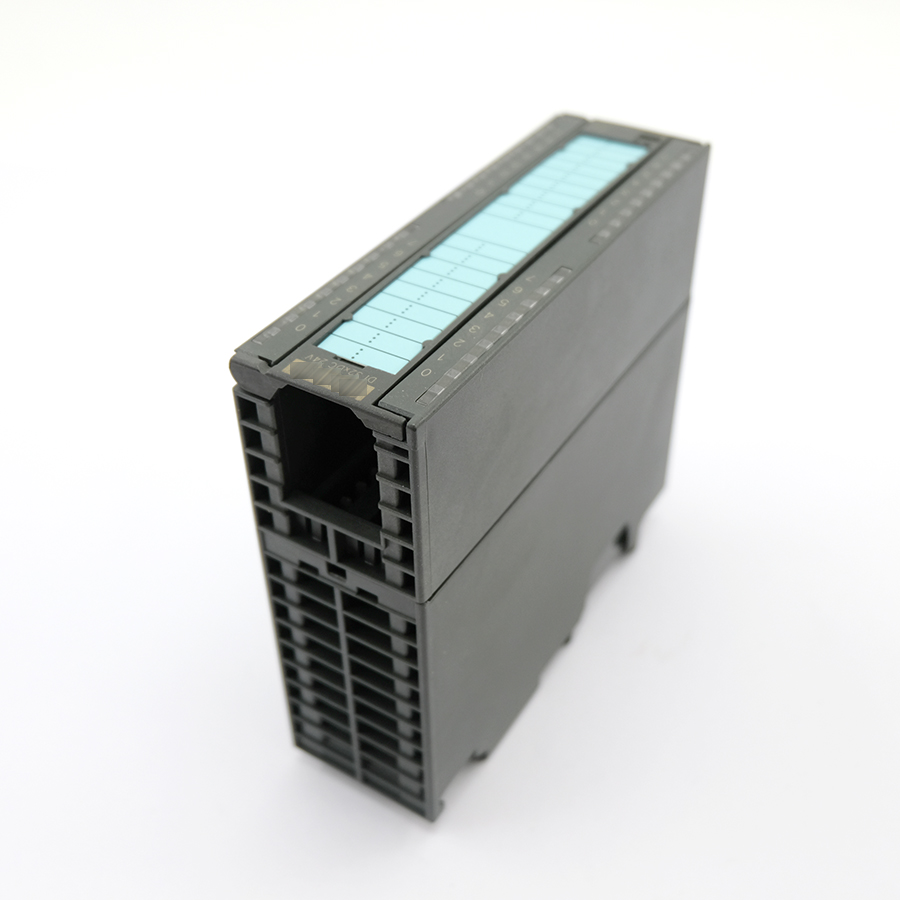
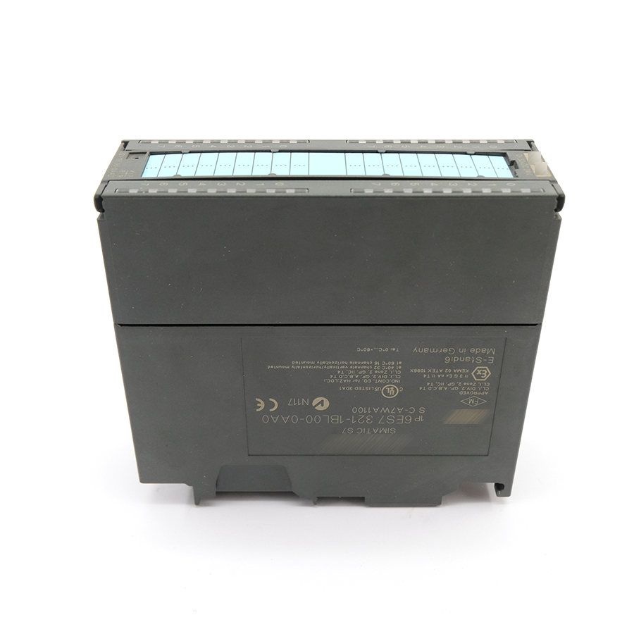
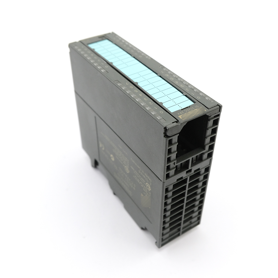
High-Density Input: Provides 32 channels of digital input on a compact module, significantly improving space efficiency and making it suitable for input-intensive applications.
-
Signal Characteristics: All 32 channels are designed to receive 24 V DC digital signals. The recognized voltage range for signal level “1” is typically 13V to 30V DC, and for signal level “0” it is typically -3V to +5V DC.
-
Diagnostic Function: The module features group diagnostics, capable of detecting a loss of the sensor supply voltage (L+). When a fault is detected, diagnostic information is written to the CPU’s diagnostic buffer and triggers an alarm in the configuration software (e.g., STEP 7/TIA Portal), allowing engineers to quickly locate the issue.
-
Electrical Isolation: All input channels are optically isolated from the backplane bus, effectively suppressing external electromagnetic interference and ensuring the safety of the CPU-side circuitry.
-
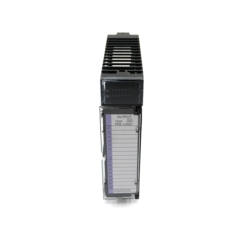
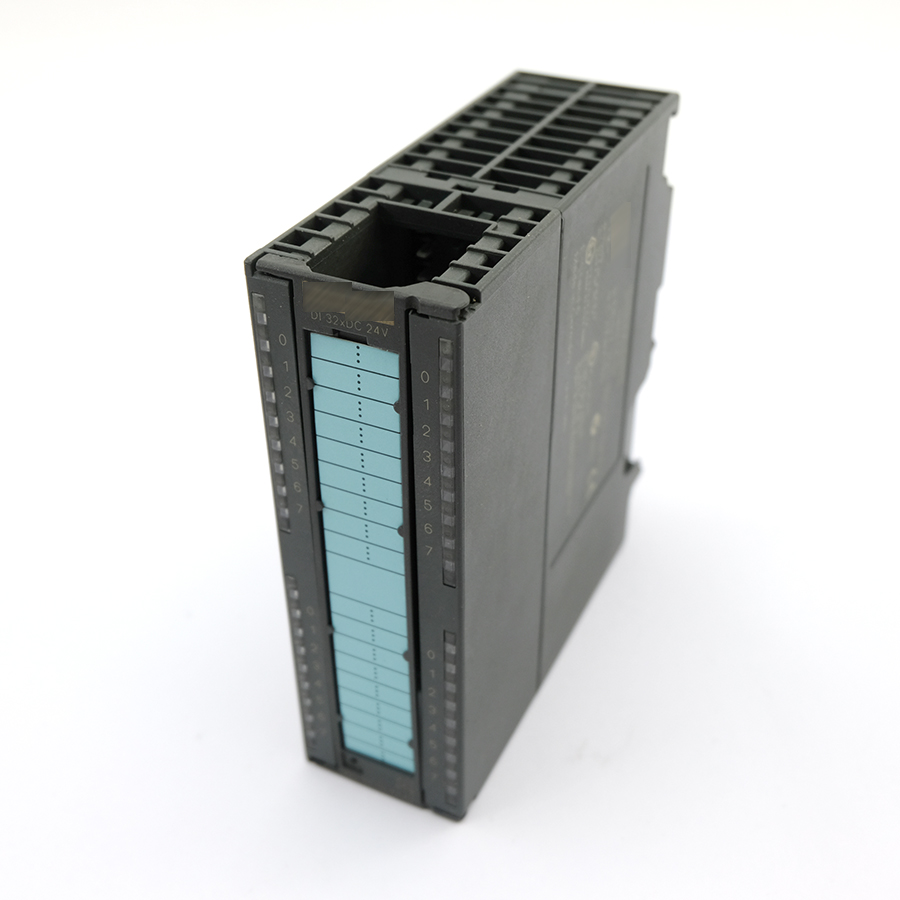
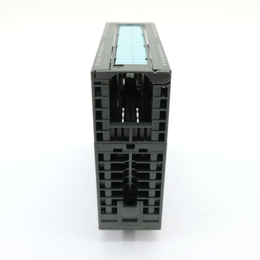
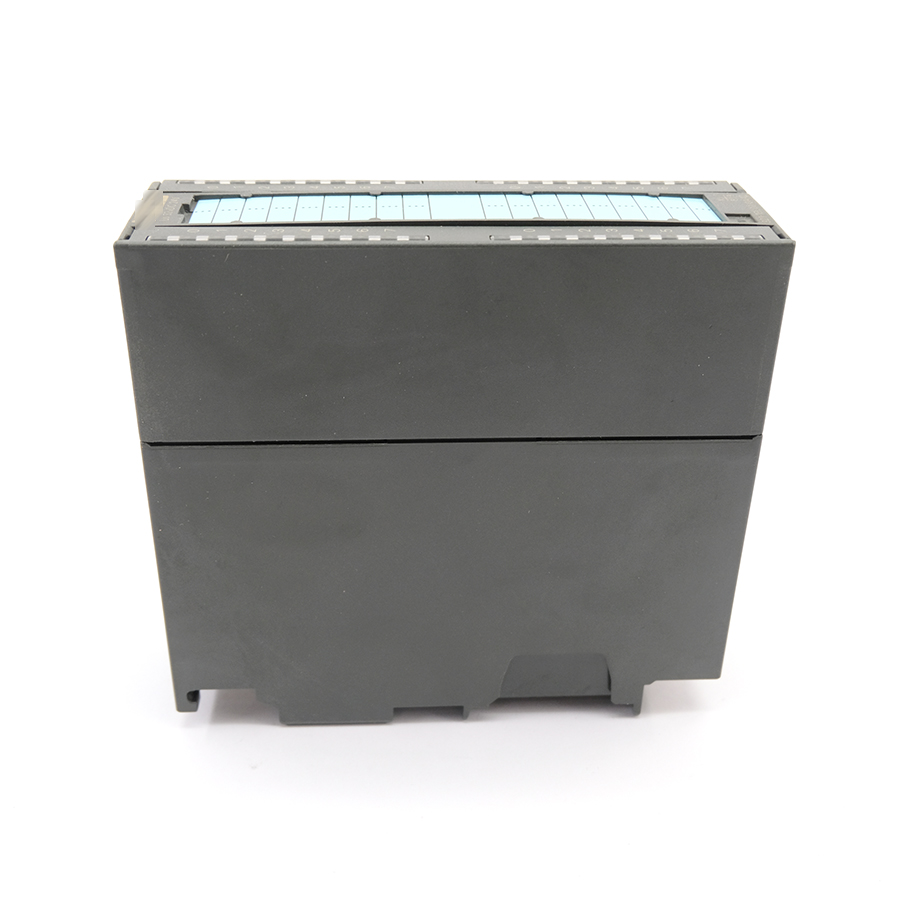
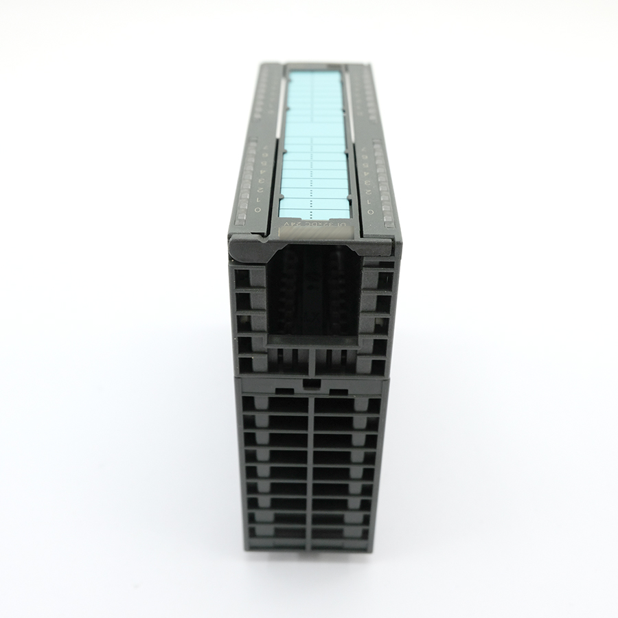
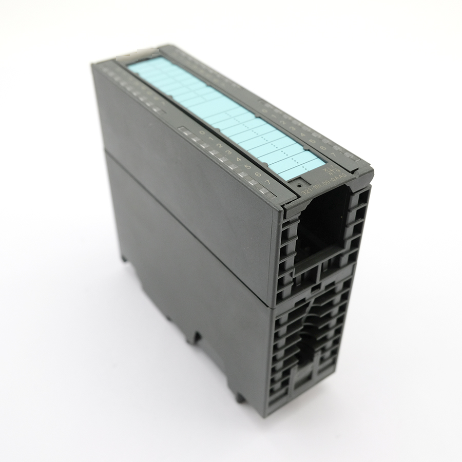
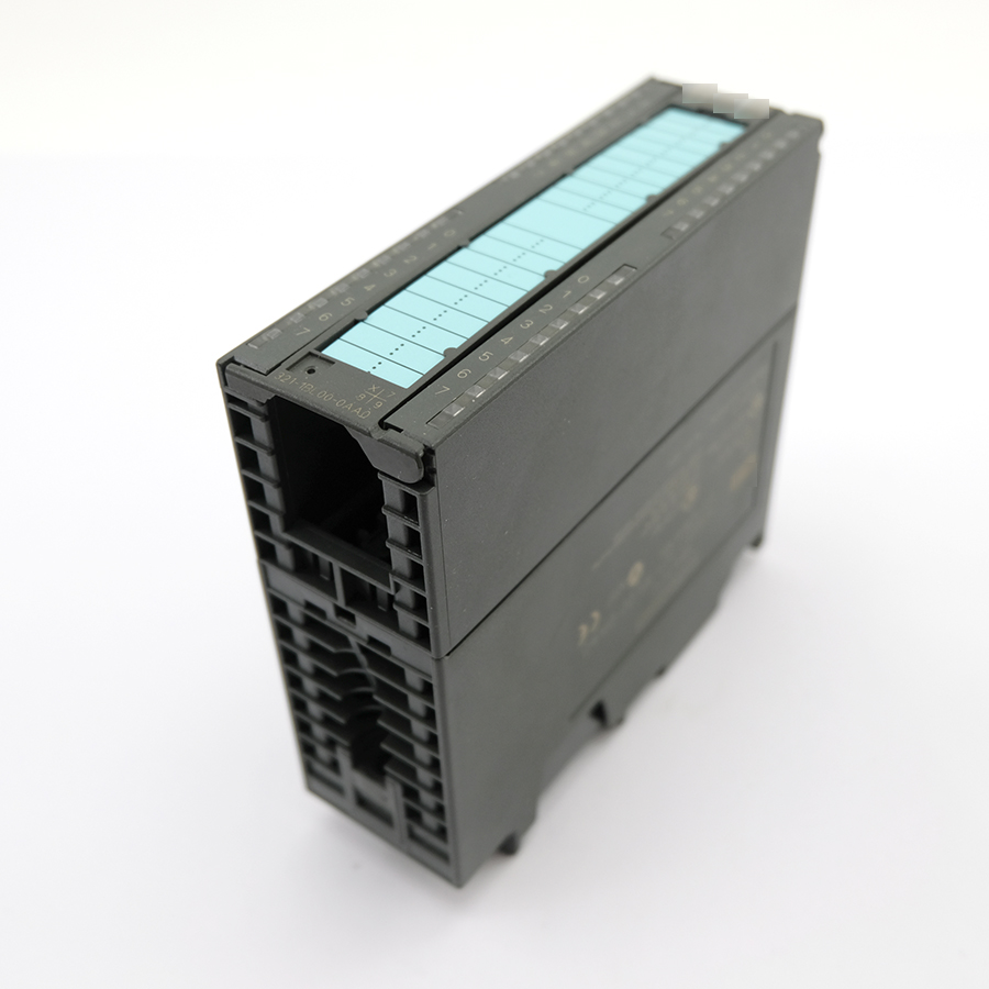
Compact and Efficient: As a standard S7-300 module, it has a width of 40 mm. It communicates with other modules via the backplane bus, is easy to install, and can be quickly integrated into an S7-300 rack.
-
Status Indication: Each input channel has an independent green LED indicator that displays the real-time signal status (ON/OFF) of the corresponding point.
Key Specifications:
| Parameter | Details |
|---|---|
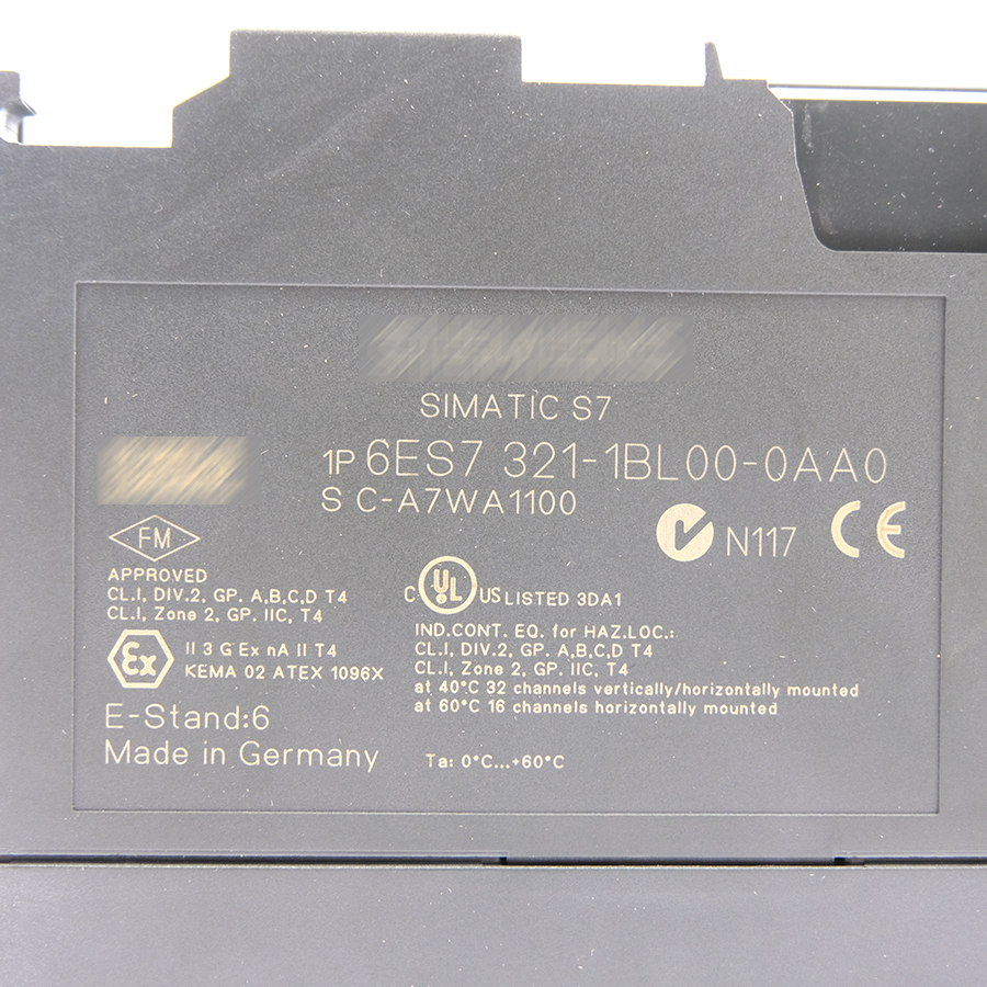
| Model | 6ES7321-1BL00-0AA0 |
| Series | SIMATIC S7-300 |
| Module Type | Digital Input (DI) |
| Number of Channels | 32 |
| Rated Input Voltage | 24 V DC |
| Signal “1” Range | 13 V DC to 30 V DC (typical) |
| Signal “0” Range | -3 V DC to +5 V DC (typical) |
| Input Current (at Signal “1”) | Typically 7 mA |
| Backplane Bus Current Consumption | Typically 110 mA |
| Power Loss | Typically 3.5 W |
| Isolation | Optical isolation between channels and backplane bus |
| Diagnostics | Group Diagnostics: Loss of Sensor Supply (L+) |
| Width | 40 mm |
| Required Engineering Software | STEP 7 (e.g., TIA Portal) |