

The analog input vs digital input choice decides how your PLC sees the plant. Digital inputs read two states — on or off. Analog inputs read a continuous range — a temperature, a pressure, a speed. Wire the wrong type and the PLC either sees nothing useful or sees noise. This guide covers how each input works, where each fits, and how to pick the right I/O module for the job.
Key Takeaways
| Question | Short answer |
|---|---|
| What does a digital input read? | Two states: on/off, 24 V DC present or not |
| What does an analog input read? | A continuous value: 4–20 mA or 0–10 V signals |
| Typical sources | Digital: pushbuttons, limit switches, proximity sensors · Analog: transmitters, thermocouples, speed references |
| Cost difference | Analog channels cost more per point and need more wiring care |
What Is a Digital Input?
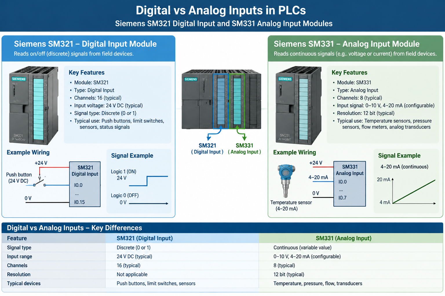
A digital input channel detects whether a voltage is present at its terminal, within defined thresholds. In industrial systems the standard is 24 V DC: above roughly 15 V the channel reads ON (logic 1); below roughly 5 V it reads OFF (logic 0). The channel only tells the program one bit of information — a button is pressed or it is not, a guard door is closed or it is not.
Typical digital input devices: pushbuttons, selector switches, limit switches, proximity sensors, photoeyes, and relay contacts. Modules come in 8, 16, or 32-channel densities — a Siemens SM321 digital input module, for example, packs 32 channels in one S7-300 slot.
What Is an Analog Input?
An analog input channel measures a signal that varies continuously and converts it to a number the PLC program can use — a 12- or 16-bit value covering the sensor’s range. The two standard industrial signal types:
- 4–20 mA current loop — the workhorse for transmitters; current signals resist electrical noise and cable resistance over long runs
- 0–10 V voltage signal — common for drives, actuators, and shorter runs
The live-zero of 4 mA is deliberate: 0 mA unambiguously means a broken wire, not a zero reading. Typical analog sources: pressure and temperature transmitters, flow meters, load cells, valve position feedback, and speed references to drives. Modules like the Siemens SM331 analog input module or the Allen-Bradley 1746-NI4 provide multiple channels with configurable signal types.
Analog Input vs Digital Input: The Real Differences
| Point | Digital input | Analog input |
|---|---|---|
| Information | 1 bit (on/off) | A measured value (e.g., 12–16 bits) |
| Signal level | Typically 24 V DC on/off | 4–20 mA or 0–10 V continuous |
| Devices | Switches, pushbuttons, basic sensors | Transmitters, meters, feedback signals |
| Wiring care | Low — twisted pair usually enough | Higher — shielding and grounding matter |
| Module cost | Low per channel | Higher per channel |
| Programming | Read a contact | Scale raw counts to engineering units |
Which Input Type Should You Choose for Your Application?
The sensor decides, not the programmer:
- Alarm or position with two states? Digital. A tank full switch does not need an analog channel.
- Need the actual value — temperature, pressure, speed? Analog, using 4–20 mA for anything beyond a few meters of cable.
- Drive speed reference or PID loop? Analog, or digital fieldbus (PROFIBUS, EtherNet/IP) if the drive supports it — one network replaces dozens of analog wires.
- Budget check: if the plant only needs on/off status, do not pay for analog channels you will never scale.
Replacing a failed I/O module and unsure whether you need the exact variant? Photograph the module’s part number and rating label. Send it to us and we will confirm the compatible replacement: [email protected] or WhatsApp +86 15107352558.
What Wiring Mistakes Cause Analog Input Problems?
Most analog input faults are installation faults:
- Unshielded cable runs beside VFD output cables — VFD switching noise rides straight into the channel. Use shielded twisted pair, grounded at one end
- Ground loops from multiple grounds on the shield and signal reference
- Wrong scaling — the module reads 4–20 mA but the program scales 0–20 mA, so readings sit 20% low across the range
- Missing loop power — two-wire transmitters need the channel’s or an external 24 V supply
Digital inputs are more forgiving, but share two failure modes: sensor leakage current holding a “leaky OFF” input ON, and contact bounce on mechanical switches (handled in software or with the module’s filter settings).
Frequently Asked Questions
What is the difference between analog and digital input?
A digital input reads two states — on or off — while an analog input measures a continuous signal such as 4–20 mA or 0–10 V and converts it to a number. Digital suits switches and status; analog suits measurements.
What is an example of a digital input?
A limit switch on a machine guard wired to a 24 V DC input channel: the PLC sees one bit telling it whether the guard is closed.
What is an example of an analog input?
A 4–20 mA pressure transmitter on a compressed air line: the PLC converts the signal to a pressure value for display, alarms, and PID control.
Why is 4–20 mA used instead of 0–20 mA?
The 4 mA live zero lets the system detect a broken wire: 0 mA means the loop is dead, not a zero reading. Current signals also resist voltage drop over long cable runs.
Can I mix digital and analog modules in one PLC rack?
Yes — that is the normal arrangement. Racks combine digital input, digital output, analog input, and analog output modules as the application demands; see our PLC module catalog for the range.
Get the Right I/O Module Fast
Whether your application needs analog input vs digital input modules — or both — we stock 100,000+ automation parts from 20+ brands, every unit tested before dispatch, with 48-hour global shipping and no minimum order. Send the module part number: [email protected] or WhatsApp +86 15107352558.